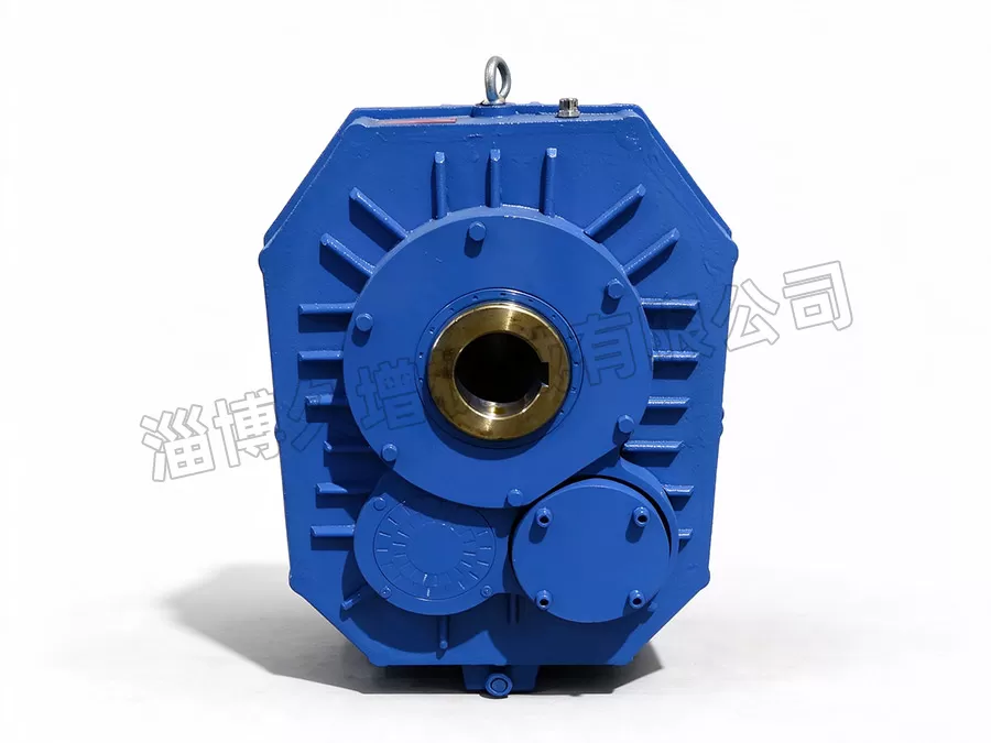
Description: The company manufactures a full range of industrial reducers and motorized pulleys. Complete specifications and abundant models are available to adapt to various industrial transmission scenarios. We also undertake custom processing of non-standard special-shaped reducers and gear equipment to meet enterprises' transmission supporting requirements.
Release Time: 2026-10-30
Views: 7
ZJ / ZJY Shaft Mounted Reducer
Manufactured in accordance with standard JB/T7337-1994. Its hollow output shaft is directly suspended onto the input shaft of the driven host machine. Two connection types are available: locking ring connection and key connection.
The ZJY212-10 shaft mounted gear reducer for cement mixers is a cylindrical gear reducer. “10” stands for the transmission ratio. It adopts two-stage transmission with hollow output shaft. The power input shaft extends directly into the interior. The reducer is suspended on the power input shaft of the matched host, eliminating intermediate connecting accessories and reducer mounting platform to save space. It is widely used for cement mixers and mixing plants, and also commonly applied in mechanical transmission of bucket elevators, belt conveyors, scraper conveyors and other equipment. It can be matched with other host machines requiring this mounting form.
Models of ZJ / ZJY Shaft Mounted Reducers
ZJY75, ZJY90, ZJY106 suspended gear reducer, ZJY125, ZJY150 shaft mounted hardened gear reducer, ZJY180, ZJY212 shaft mounted gear reducer, ZJY250, ZJY300 hardened tooth surface shaft mounted cylindrical gear reducer;
ZJ63, ZJ100, ZJ160, ZJ250, ZJ400, ZJ630 hardened gear reducer.
Besides bidirectional rotation, ZJY series shaft mounted reducers can be equipped with backstop devices for unidirectional braking.
The whole series is sized by the centre distance of the low-speed stage (mm), with nine frame sizes: 75, 90, 106, 125, 150, 180, 212, 250, 300. Each frame has nine reduction ratios: 10, 11.2, 12.5, 14, 16, 18, 20, 22.4, 25. The reducer marking code includes model, low-speed stage centre distance, nominal reduction ratio and rotation direction.
Operating Conditions
Input shaft speed ≤ 1500 r/min;
Ambient temperature: -20℃ ~ +45℃. If ambient temperature is below 0℃, an oil heating device must be used to raise oil temperature above 0℃ before startup.
Forward and reverse rotation is available.
Parameters of ZJY212
Weight: approx. 173 kg; output torque: 6000 N·m. At ratio 14 and input speed 1500 r/min, output speed = 107 r/min; nominal input power: 65 kW.
Overall dimensions: width 277 mm, height 625 mm, length 477 mm; input shaft diameter 48 mm; centre distance 160 mm; torque arm adjustment range: 540–860 mm.
For unidirectional rotation with backstop: allowable speed 690 r/min, allowable backstop torque 550 N·m.
It adopts direct suspension mounting on the host input shaft, removing connecting parts and mounting base. Suitable for bucket elevators, belt conveyors, scraper conveyors and other machinery. Manufactured to ZBJ9009-88. Major transmission parts are made of high-quality alloy steel. Gears are carburized, quenched and precision ground to Grade 6 per GB10095-88. Features compact structure, high load capacity, long service life, low noise and high efficiency. Compared with ZJ series, ZJY weighs only about 30% of ZJ at the same output torque, greatly lowering rigidity requirements for the host frame and ensuring smooth transmission. Besides bidirectional running, backstop can be fitted on request for unidirectional braking.
ZJY series has nine frame sizes based on low-speed centre distance: 75, 90, 106, 125, 150, 180, 212, 250, 300. Each size has nine ratios: 10, 11.2, 12.5, 14, 16, 18, 20, 22.4, 25. Rotation directions: counter-clockwise, clockwise, reversible.
Installation & Operation Instructions
1. The reducer is generally suspended vertically or within ±20° from vertical for matching with host equipment.
2. Before fitting the output bore onto the host shaft, apply grease on shaft and bore surfaces to reduce assembly resistance. Never hammer forcibly, otherwise bearings may be damaged or hollow shaft end deformed. For reducers with double taper sleeve mounting, follow this procedure:
(1) Fit the inner hollow taper sleeve onto the main shaft of the host;
(2) Slide the reducer onto the main shaft and rest its left side on the left taper sleeve;
(3) Install the right taper sleeve from the right side;
(4) Tighten the fastening screws of both taper sleeves alternately.
3. V-belt installation. Due to compact structure and relatively small bearings, observe the following rules:
(1) Prefer high-strength narrow V-belts. Narrow V-belts reduce pulley width, outer diameter and belt tension, bringing the tension point closer to the inner side of the input shaft bearing and extending bearing service life.
(2) Use fully machined V-belt pulleys. Pulleys with lightening holes shall meet static balance requirements.
(3) Adjust belt tension properly. A simple check: press the belt with two fingers; the deflection should be 1–2 mm. Belts stretch and slip after running, so re-tension them later. Do not over-tension during initial installation to avoid extra cantilever load on input shaft bearings.
4. A torque arm is normally fitted to counteract the reaction friction torque of hollow shaft bearings acting on the housing. The mounting position of the torque arm is shown in Figure 1. An OO-type open turnbuckle is recommended (see Appendix 2). If the eyelet bore is non-standard, replace it with a machined eyelet. The fit between eyelet bore and pin is H9/n9. Small clearance fit reduces side-to-side shaking of the reducer.
5. Remove the oil plug at the middle of the housing. Keep the reducer vertical. Fill N220 medium extreme-pressure gear oil through the lifting ring hole until oil flows out from the lower oil plug.
6. Run the reducer with no load for a period. Check for abnormal noise, oil leakage or vibration before applying full load.
7. Replace lubricating oil after the first 300–600 operating hours. Afterwards, change oil every 1500–5000 hours depending on working conditions, maximum interval not exceeding 18 months. Clean the magnetic oil plug (at housing bottom) during each oil change.
8. Stop operation immediately if oil temperature rises sharply or abnormal noise occurs. Resume operation only after faults are eliminated.
9. To switch a unidirectional backstopped reducer to reversible operation: remove the end cover opposite the input shaft. For constant-contact backstops, pull out the star wheel with a pull plate (custom-made according to lifting screw holes on the star wheel) and reassemble it reversely; or remove rollers, pins and springs at star wheel notches (small sizes may not have these parts). For non-constant-contact backstops, pull out and reverse the backstop body and outer ring.
10. The hollow shaft end cover is used for axial positioning and disassembly. For fixing: fasten to the host input shaft using hex bolts matching the bore size. For disassembly: screw hex bolts into the threaded holes on both sides to push out the housing.
